- Cisco Community
- Technology and Support
- Networking
- Switching
- LAN Design Help
- Subscribe to RSS Feed
- Mark Topic as New
- Mark Topic as Read
- Float this Topic for Current User
- Bookmark
- Subscribe
- Mute
- Printer Friendly Page
- Mark as New
- Bookmark
- Subscribe
- Mute
- Subscribe to RSS Feed
- Permalink
- Report Inappropriate Content
08-15-2007 07:02 PM - edited 03-05-2019 05:55 PM
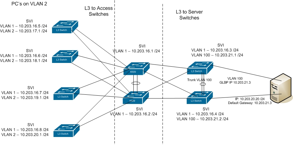
I am re-designing my current network and am pretty much replacing all of our LAN gear. I will have dual 6509?s at the core, and pushing a mix of 4507?s and 6509?s to my access layer. I also want to move my servers off of the core and put them on their own L3 switch. The goal is to provide redundancy and to eliminate STP wherever possible.
The attached diagram is a work in progress and I would like to verify that my thinking is correct. For simplistic purposes, I am using VLAN1 for mgt and a /24 for all networks. This will most likely change in the future.
The dual core 6509?s will each have SVI ? VLAN 1 configured and connected by an etherchannel. Each access switch and server switch will have their VLAN 1 configured with an address in the same network.
Each core will connect to each access switch and the uplink ports on both the core and access switch will be in VLAN 1. The access switches will then have SVI - VLAN 2 configured and all pc?s will connect to access ports in this VLAN. The DG for the pc?s will be VLAN 2?s SVI IP address on the switch that they connect to.
Each core will connect to the server switches and the uplink ports on both core and server switch will be in VLAN 1. The server switches will then have SVI ? VLAN 100 configured. I would like to allow the servers to connect to each switch for redundancy. In order to do this, I setup an etherchannel between the server switch and am trunking VLAN 100 only. I will then setup glbp or vrrp between the server switches. This will allow for the servers to be teamed and use 1 address with a connection to each switch. If I use glbp, the server?s default gateway will be the glbp IP.
I will run EIGRP on all L3 switches.
Will this design work? If I use glbp and the server nics are teamed, am I correct that I should use the fault tolerant mode where only one nic transmits and receives. I could then alternate the switch that each active nic plugs in to (server 1 active nic to sw1, server 2 active nic to sw2, etc).
Solved! Go to Solution.
- Labels:
-
Other Switching
Accepted Solutions
- Mark as New
- Bookmark
- Subscribe
- Mute
- Subscribe to RSS Feed
- Permalink
- Report Inappropriate Content
08-16-2007 01:50 PM
i think you did explain it correctly, i think it's me that didn't explain it properly.
In the above example you give you are not routing from the core switch to the access-layer switch, you are in fact switching.
Think of it like this. A client on access-layer switch 1 want to talk to a server which is in vlan 100 connected to your server switches.
The client needs to send the traffic to it's default gateway. Again using your example lets say the client is 172.16.5.10. So it sends the traffic to it's default gateway which is 172.16.5.254.
Now that switch needs to send the traffic towards the core 6500. But it doesn't route that traffic to the core 6500, it switches it and it has to switch it because the IP address on the core switch is in the same vlan. The actual routing between the vlans takes place on the 6500's.
So you have L2 switching from the access-layer to the 6500 switches.
Now if it is a point to point link, again the traffic goes to the default gateway but now the traffic is not switched because that vlan does not extend across the uplinks.
Does this make sense ?
Jon
- Mark as New
- Bookmark
- Subscribe
- Mute
- Subscribe to RSS Feed
- Permalink
- Report Inappropriate Content
08-16-2007 04:29 AM
Hi
No it will not work as it is but with a few modifications it will.
There are a couple of key problems.
Firstly vlan 2 exists on each access-layer switch. The access-layer switches are connected to the 6500's with L3 links. So there are 2 issues with this
i) a client in vlan 2 on one of your access-layer switches cannot communicate with a client in vlan 2 on another switch. This may or may not be an issue for you.
You switch from a client in one vlan to a client in the same vlan, you do not route. But you have no layer 2 path between your access-layer switches.
ii) What will be an issue is that each of your 6500 switches will see 4 equal cost paths to vlan 2 as you have EIGRP adjacencies between the access-layer switches and the core 6500's. So how will the 6500 know which link to send the traffic down to get to a vlan 2 client. Remember that the links are L3 so there will no mac-address entries on the 6500 switches for the clients.
The second problem is with your vlan 1. The same principle applies that because you have separated your switches with L3 links each vlan 1 interfaces is in effect in it's own subnet.
Solutions to the above are
1) For the client vlans create a unique vlan per access-layer switch. You still create the vlan interface on the access-layer switch and the routing will take care of the rest.
2) For vlan 1 management. If you are going to separate all switches with L3 links you may as well use loopbacks for managing your switches rather than vlna interface.
Obviously the above does not apply to vlan 100 which is used by the servers and needs to be resilient between the 2 switches.
HTH
Jon
Edit - attached is a link to designing a fully routed campus solution. Have a look as a lot of what you are trying to do is in there.
http://www.cisco.com/en/US/netsol/ns656/networking_solutions_design_guidances_list.html#anchor2
- Mark as New
- Bookmark
- Subscribe
- Mute
- Subscribe to RSS Feed
- Permalink
- Report Inappropriate Content
08-16-2007 05:07 AM
1) So the VLAN numbers must be different on each access switch even though they have a separate network assigned to VLAN 2 on each switch?
2) Once I remove the IP address from VLAN 1 and assign them to a loopback interface, I have essentially created a L3 routed interface and EIGRP will then know which link to send traffic down?
Thanks for the explanation.
- Mark as New
- Bookmark
- Subscribe
- Mute
- Subscribe to RSS Feed
- Permalink
- Report Inappropriate Content
08-16-2007 05:14 AM
1) Oops my mistake. Sincere apologies i only looked at the vlan number and not the subnet range.
Yes this would work although i think i would still use different vlan numbers if only to avoid confusing simple people like me :)
2) Yes.
Apologies once again
Jon
- Mark as New
- Bookmark
- Subscribe
- Mute
- Subscribe to RSS Feed
- Permalink
- Report Inappropriate Content
08-16-2007 05:48 AM
No problem. Thanks for clearing this up!
One more question if I may:
This will take care of the LAN design. When I connect my WAN routers, I will connect one Ethernet port to each core just like my server and access switches.
If I understand you correctly from the LAN design, I will have to create a router interface on each switch (no switchport) and assign an IP address to each interface. I can not use an SVI since EIGRP will not know which interface to route traffic to. Is that correct? For every router (I only show 2 in the diagram), I will have to create a new L3 port on each core and add the next IP in the network. A /28 or /29 would be best suited for this.
Thanks again.
- Mark as New
- Bookmark
- Subscribe
- Mute
- Subscribe to RSS Feed
- Permalink
- Report Inappropriate Content
08-16-2007 05:57 AM
You can use a vlan to interconnect all your routers if you want and this would work. So you could have each router interface connecting to the 6500 switches in the same vlan with an IP address out of the same subnet.
Depending on your WAN topology EIGRP would just see multiple paths potentially to the same destination but without knowing your topology it's difficult to say.
Alternatively, if you have the addressing you could stick with your overall L3 design and hav point to point links from each router interface. You would only need a /30 per router to 6500 connection.
We do the L3 connections in our data centre but it does depend on how many connections and how much addressing you have.
One last thing. If you are running EIGRP across your WAN make sure you are summarising correctly out onto the WAN.
HTH
Jon
- Mark as New
- Bookmark
- Subscribe
- Mute
- Subscribe to RSS Feed
- Permalink
- Report Inappropriate Content
08-16-2007 06:13 AM
Great, thanks. That is good info.
Now that I think about it, we are doing the SVI config today. We just never use both paths since one router has 8 T1's in a MLPP bundle while the other has a full DS3.
Our end design is to go into dual carrier MPLS clouds through 2 routers. We will be replacing our existing 2 routers with 2 for MPLS connection. Until we get there, we will have a total of 4 wan routers.
It would seem easier to me to create the 1 SVI on each core and then dual connect to each router using an IP in the corresponding network. This would eliminate all the /30 links. Less confusion for me!!!
Thanks again for the info!
- Mark as New
- Bookmark
- Subscribe
- Mute
- Subscribe to RSS Feed
- Permalink
- Report Inappropriate Content
08-16-2007 07:03 AM
This is a dumb question, but after going back through this, I'm confused on how the access network will route to the core.
Is simply assigning a loopback address on each switch and then adding the loopback to EIGRP enough to tell the access switches where to route the traffic? I would think that I would have to do a no switchport and assign an IP Address to each interface that uplinks to an access switch.
I think I have been looking at this to long?.
- Mark as New
- Bookmark
- Subscribe
- Mute
- Subscribe to RSS Feed
- Permalink
- Report Inappropriate Content
08-16-2007 09:28 AM
Your loopback interface is purely for managing the switch.
You still need to use a point to point link between each access-layer switch and the core 6500 switches ie.
each access-layer switch will have a P2P link to core switch and a P2P link to core switch 2. You can use /30's for these links.
HTH
Jon
- Mark as New
- Bookmark
- Subscribe
- Mute
- Subscribe to RSS Feed
- Permalink
- Report Inappropriate Content
08-16-2007 12:48 PM
Ok, thanks. After reading one of the pdf's in the link you sent, I found where it explained this.
My last question is, what is the downside to just using two of the addresses in the access layer instead of using a /30. If core 1 interface ip is 17.1, core 2 interface 17.2, and the SVI on the access layer is 17.3. This would eliminate the need for the /30.
- Mark as New
- Bookmark
- Subscribe
- Mute
- Subscribe to RSS Feed
- Permalink
- Report Inappropriate Content
08-16-2007 12:55 PM
Okay i think i understand what you are asking ie.
instead of having 2 point to point links from each access-layer switch which uses 4 addresses, 2 on the access-layer switch and 2 on the core switches, why not just use a vlan and have just one IP address on the access-layer switch.
If i have understood correctly you can but then this is no longer a layer 3 access-layer because you are now extending a vlan across the links from your core switches to your access-layer switches.
Jon
- Mark as New
- Bookmark
- Subscribe
- Mute
- Subscribe to RSS Feed
- Permalink
- Report Inappropriate Content
08-16-2007 01:22 PM
Maybe I didn't explain it correctly. It should be L3 to the access unless I totally missed the boat.
Let me explain it with using one of our sister companies as an example. All ports are configured as access ports with no vlan assignments (VLAN 1). The SVI VLAN 1 is configured on these access switches with the last address in the user network. 2 access ports then connect to each core (1 to each core). The L3 interfaces on the Core's are configured with an address in these networks as well:
User network 1 - 172.16.5.0 /24
SVI on switch - 172.16.5.254 /24
Core 1 int IP - 172.16.5.1 /24
Core 2 int IP - 172.16.5.2 /24
Each access layer switch and the Core 1 and 2 interfaces are configured the same way except on different /24 networks:
User network 2 - 172.16.6.0 /24
SVI on switch - 172.16.6.254 /24
Core 1 int IP - 172.16.6.1 /24
Core 2 int IP - 172.16.6.2 /24
User network 3 - 172.16.7.0 /24
etc........
- Mark as New
- Bookmark
- Subscribe
- Mute
- Subscribe to RSS Feed
- Permalink
- Report Inappropriate Content
08-16-2007 01:50 PM
i think you did explain it correctly, i think it's me that didn't explain it properly.
In the above example you give you are not routing from the core switch to the access-layer switch, you are in fact switching.
Think of it like this. A client on access-layer switch 1 want to talk to a server which is in vlan 100 connected to your server switches.
The client needs to send the traffic to it's default gateway. Again using your example lets say the client is 172.16.5.10. So it sends the traffic to it's default gateway which is 172.16.5.254.
Now that switch needs to send the traffic towards the core 6500. But it doesn't route that traffic to the core 6500, it switches it and it has to switch it because the IP address on the core switch is in the same vlan. The actual routing between the vlans takes place on the 6500's.
So you have L2 switching from the access-layer to the 6500 switches.
Now if it is a point to point link, again the traffic goes to the default gateway but now the traffic is not switched because that vlan does not extend across the uplinks.
Does this make sense ?
Jon
- Mark as New
- Bookmark
- Subscribe
- Mute
- Subscribe to RSS Feed
- Permalink
- Report Inappropriate Content
08-16-2007 05:45 PM
ahhh...I understand. Wow, I was way off. Thanks for the explanation.
So this is my final question? :-)
I?m planning for the future here, so bear with me. We will be moving to a complete IPT system at some point down the line. All of our new LAN gear has PoE capabilities for the future IP Phones. I have not researched the actual switch configs as we are still at the planning phases for this piece.
I know that these (Cisco) IP phones act as a switch for the pc?s. The switchport that the phone uplinks to at the access layer will have the voice VLAN set as well as the pc access VLAN (among other qos/cos configuration).
If we are uplinked to the core over L2 as in the previous example, will I now need to setup a trunk to carry the voice and data VLAN?s, or does Cisco handle this differenltly?
- Mark as New
- Bookmark
- Subscribe
- Mute
- Subscribe to RSS Feed
- Permalink
- Report Inappropriate Content
08-16-2007 06:01 PM
No problems with how many questions you ask, i just might not be able to answer all of them !
We used the routed access-layer design in one of our new buildings because of VOIP. We use Nortel phones but the principles are pretty similiar. I should warn you i'm not an IPT expert and there are a lot of people who use these forums that know a lot more about IPT than i do but i'll answer what i can.
Our switchports on our 4500 access-layer switches are configured with both a voice and a data vlan.
It shouldn't matter whether you span a vlan across your uplinks or whether you use P2P subnets i don't believe you would need to trunk across the uplink.
The principle of what you are trying to do still stands ie. terminate the L3 SVI for the client vlans at the access-layer.
Jon
Find answers to your questions by entering keywords or phrases in the Search bar above. New here? Use these resources to familiarize yourself with the community:
