- Cisco Community
- Technology and Support
- Networking
- Networking Knowledge Base
- Experience the Installation of a Cisco 4507R+E with Redundant Supervisor Engines (WS-X45-SUP7L-E) an...
- Subscribe to RSS Feed
- Mark as New
- Mark as Read
- Bookmark
- Subscribe
- Printer Friendly Page
- Report Inappropriate Content
- Subscribe to RSS Feed
- Mark as New
- Mark as Read
- Bookmark
- Subscribe
- Printer Friendly Page
- Report Inappropriate Content
04-30-2013 12:53 PM - edited 03-01-2019 04:55 PM
This technical document has been reproduced with the permission of www.Firewall.cx.
Firewall.cx is world's only official Cisco Press reviewer partner and is officially recommended by the Cisco Network Academy. With over 900 articles covering general networking concepts, protocol analysis, network security, Cisco Switching, VPN networks, Routers, Firewalls, Voice over IP (CallManager, CallManager Express), Wireless and other complex Cisco technologies, it’s one of the most recognised, reliable and up-to-date sources of information on the Internet. Cisco Systems CCIE and CCNP engineers frequently contribute to Firewall.cx as expert guest writers.
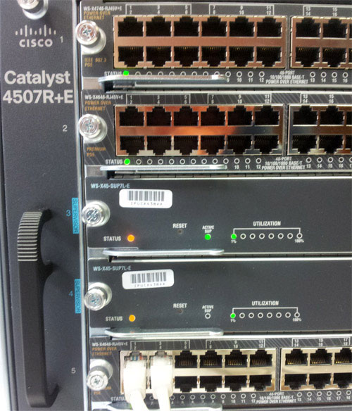
The Cisco Catalyst 4507R+E Switch
 It's no news that we here at Firewall.cx enjoy writing about our installations of Cisco equipment and especially devices that we don’t get to see and play with every day. Today we cover the installation of a new Cisco 4507R+E Catalyst switch populated with two 7L-E Supervisor engines, three WS-X4648-RJ45V+E 48 Gigabit PoE line cards and two 4200Watt power supplies with the ability to cover full future PoE requirements of the switch, when fully populated with PoE line cards.
Many might be aware of our first 4507R article that covered the installation of a Cisco Catalyst 4507R-E switch. Since then, Cisco has replaced the 4507R-E with the newer 4507R+E chassis and introduced new Supervisor Engines. The difference between the two chassis is that the 4507R-E supports up to 24Gbps bandwidth per slot, whereas the newer 4507R+E supports up to 48Gbps per slot, bringing the chassis up to date with the new market trends and high-connectivity speed requirements of enterprise companies.
To make things more interesting, we ensured we captured as many pictures as possible from our 4507R+E switch installation so that our readers can familiarise themselves with it as much as possible.
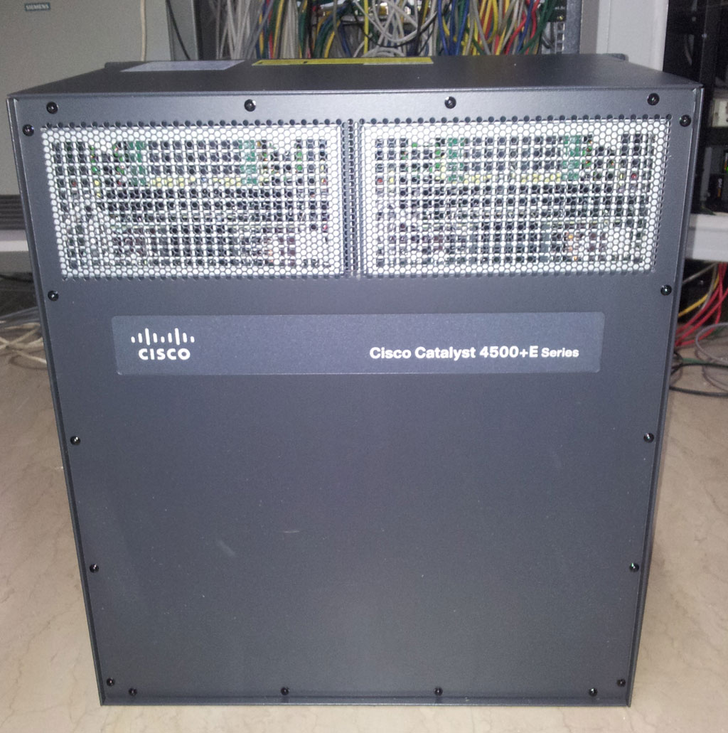
After unpacking and looking at the back of the switch chassis we noticed that not much has changed except that its label now mentions 4500+E Series, indicating that it is the newer +E series. On the front side, the fan tray manages to give away that this is the newer series as it too is labelled Catalyst 4507R+E. Apart from these minor cosmetic changes the switch looks exactly the same as its predecessor.
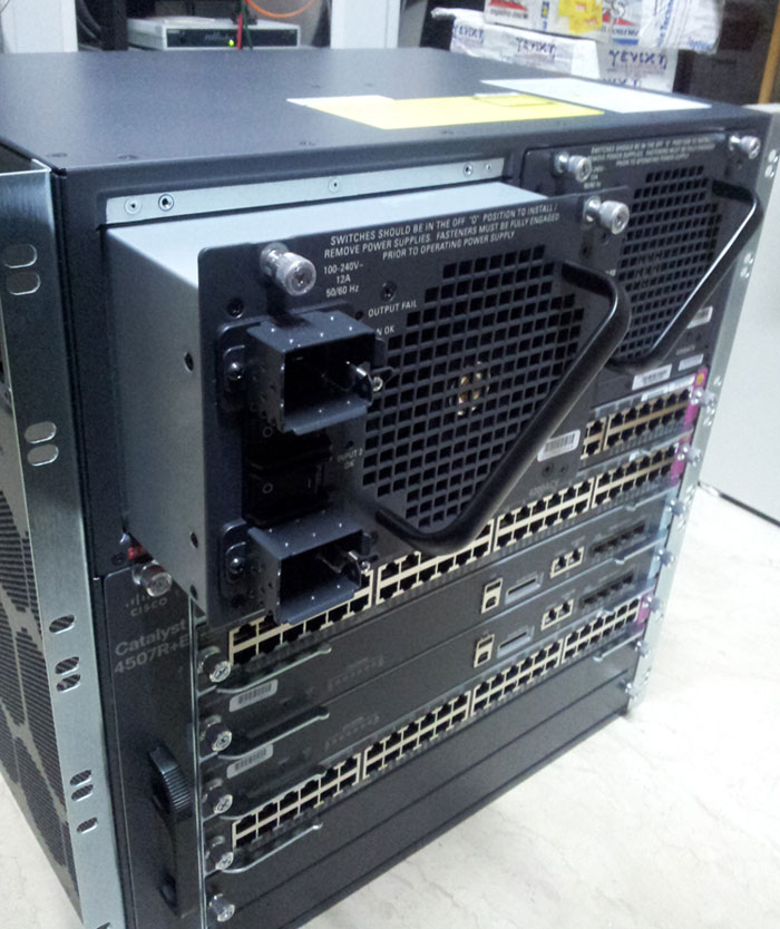
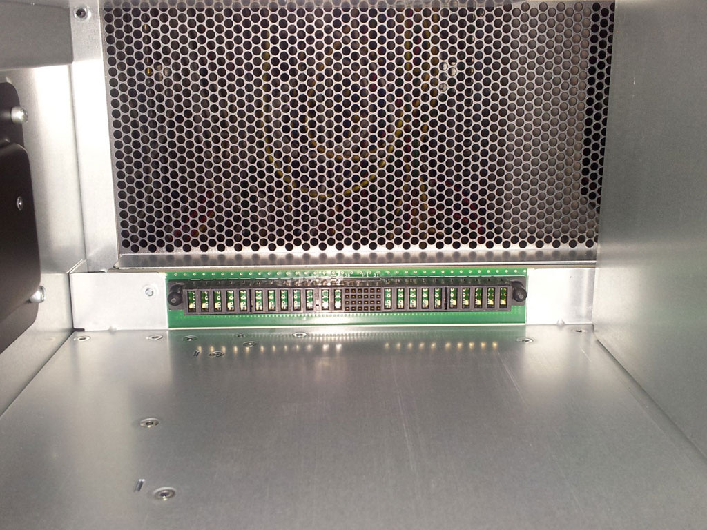
The picture below shows the back of the Cisco 4507R+E chassis. The dual power supplies are positioned at the top part of the switch and the specially designed grid allows adequate air to be pumped through the power supplies and out the back, with the help of the massive power supply fans. The fans used are extremely high quality with very little friction – when during our test run, we switched off the power supplies, the fans continued to spin for at least another 20 seconds before coming to a complete stop:
Mounting a Catalyst 4500 into a rack can be a daunting experience, mainly due to its weight. When fully populated, the switch can weigh up to 55 Kgs and requires at least two people to safely pick up and place the switch into the rack, then you’d need one more person to tighten the necessary screws to keep it inside the rack!
We also found it necessary for the rack to have adequate spacing above and below the area where the switch is to be placed, because it’s very difficult to keep the switch steady during installation because of its weight. In addition, it is imperative the rack’s side covers can be removed so the two handles on the switch (one on each side) are accessible.
To overcome the problem of installing the heavy switch, we decided to remove both power supplies and all cards from the chassis. The empty chassis made things much easier.
Revealing The Magnificent Cisco 4507R+E Backplane
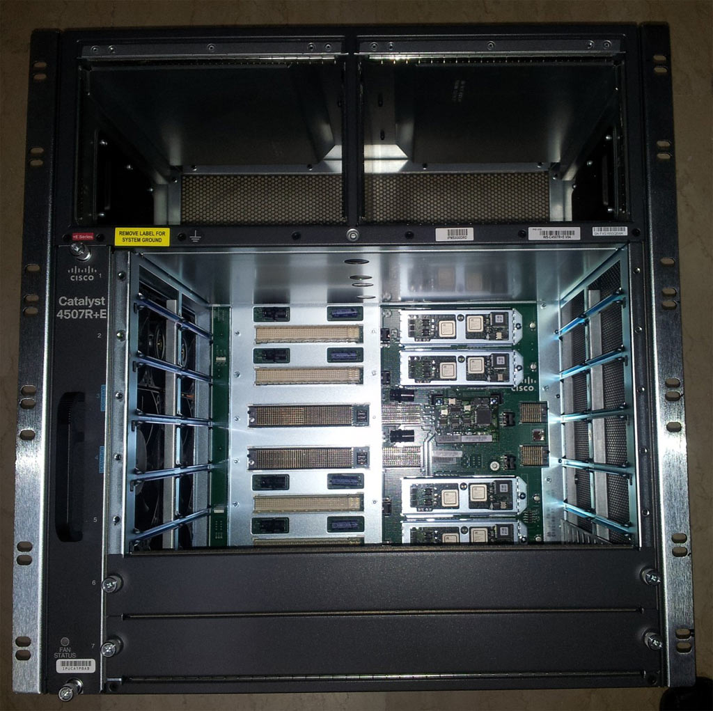
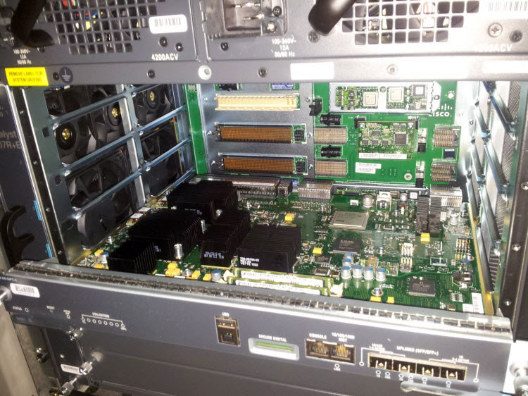
As we begun to slowly remove the switch’s power supplies, line cards and Supervisor Engines, we had a clear view of the spectacular 4507R backplane! The backplane is the switch’s ‘spine’, responsible of interconnecting all components together. Naturally, we had to capture this moment and here it is in all its glory:
We should note that extreme caution must be given when removing and inserting the 4507 cards. The engineer performing the procedure must be properly grounded and the cards must be placed on antistatic mats or, even better, inside antistatic bags. This will help avoid electrostatic discharge that can possibly damage the line cards or supervisor engines.
After removing all five cards we had a clear view of the 4507R+E’s backplane – something you don’t get to see every day. On the left side of the backplane the white and black sockets caught our attention – these are the connectors for the line cards and supervisor engines (marked in red). The Supervisor Engine sockets extend to the far right to a total of three sockets per Supervisor Engine:
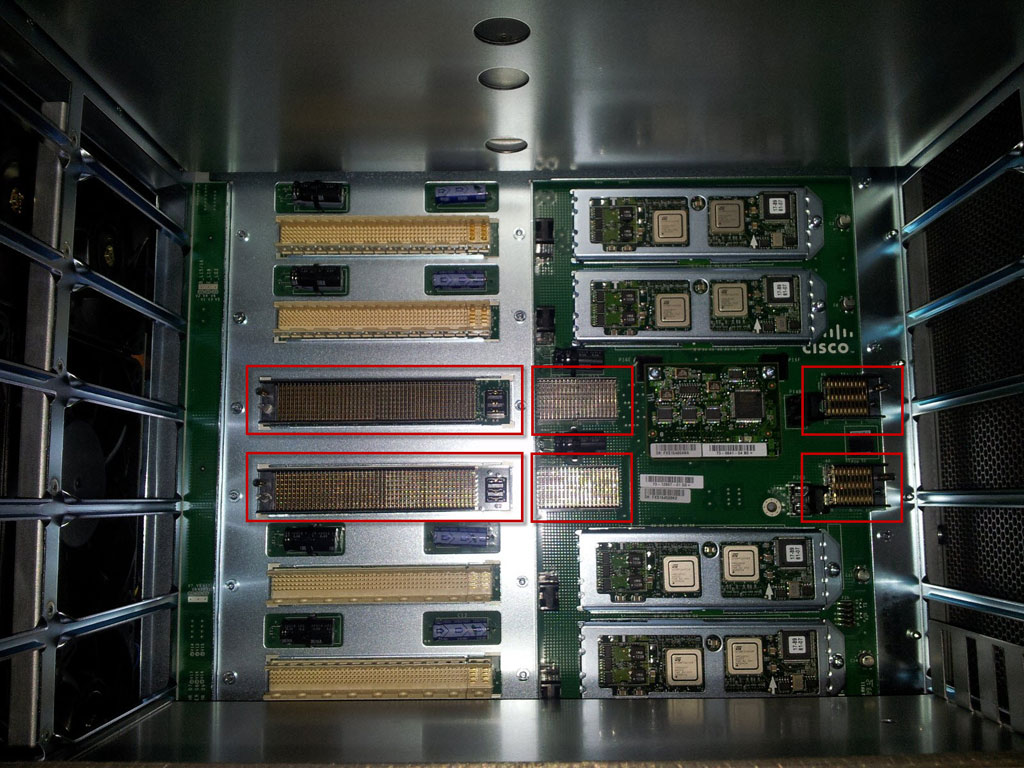
Looking to the left, the strategically placed fan tray is visible, ready to blow cool air into the chassis and directly on all cards. As shown in our picture the fan tray consists of two larger fans on the same level as the Supervisor Engines, and six smaller fans taking care of the cooling for the rest of the line cards:

Obviously the most critical cards are the Supervisor Engines, generating most of the heat under intensive workload.
Introducing The WS-X45-SUP7L-E Supervisor Engine
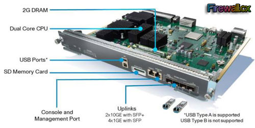
The Supervisor Engine is the heart of every modular Cisco 4500 and 6500 series switch. The Supervisor Engine 7L-E provides a number of enhancements over its predecessor Supervisor Engine 6L-E, making it a primary choice for Enterprise-class networks seeking unprecedented performance.
Following are key innovations offered by the Supervisor Engine 7L-E:
- 520Gbps system performance with 48Gpbs per slot to every line-card slot and 225mpps throughput
- Dual 10Gigabit Ethernet uplinks (via SFP+ optics) or four Gigabit Ethernet uplinks (via SFP optics)
- Application visibility through Flexible NetFlow (FNF) supporting Layer 2/3/4 information and synthetic traffic monitoring with IP SLA
- Cisco IOS XE Software which provides the ability to host third-party applications
- Support of 802.3az Energy Efficient Ethernet (EEE) capable line cards
- First and only modular switch with 8 bidirectional line-rate SPAN/RSPAN sessions
- Supports up to 244 ports 10/100/1000 in a 7-slot chassis
- External USB & SD card support for flexible storage options
- Maximum resiliency with redundant components, Nonstop Forwarding/Stateful Switchover (NSF/SSO), and In-Service Software Upgrade (ISSU) support
- Full backward compatibility with 6 G, 24 G, and 48 Gbps slot line cards with no performance degradation
Product Datasheet for the Supervisor Engine 7L-E can be found in our Cisco Catalyst 4500-6500 Supervisor Engine download section
Our users can refer to our popular Cisco Catalyst 4500 Series Zero-Downtime IOS Upgrade Process for Supervisor Engine 7-E, 7L-E, 6L-E and V-10GE Redundant Configurations article to learn how to upgrade their Supervisor Engine without network service interruption.
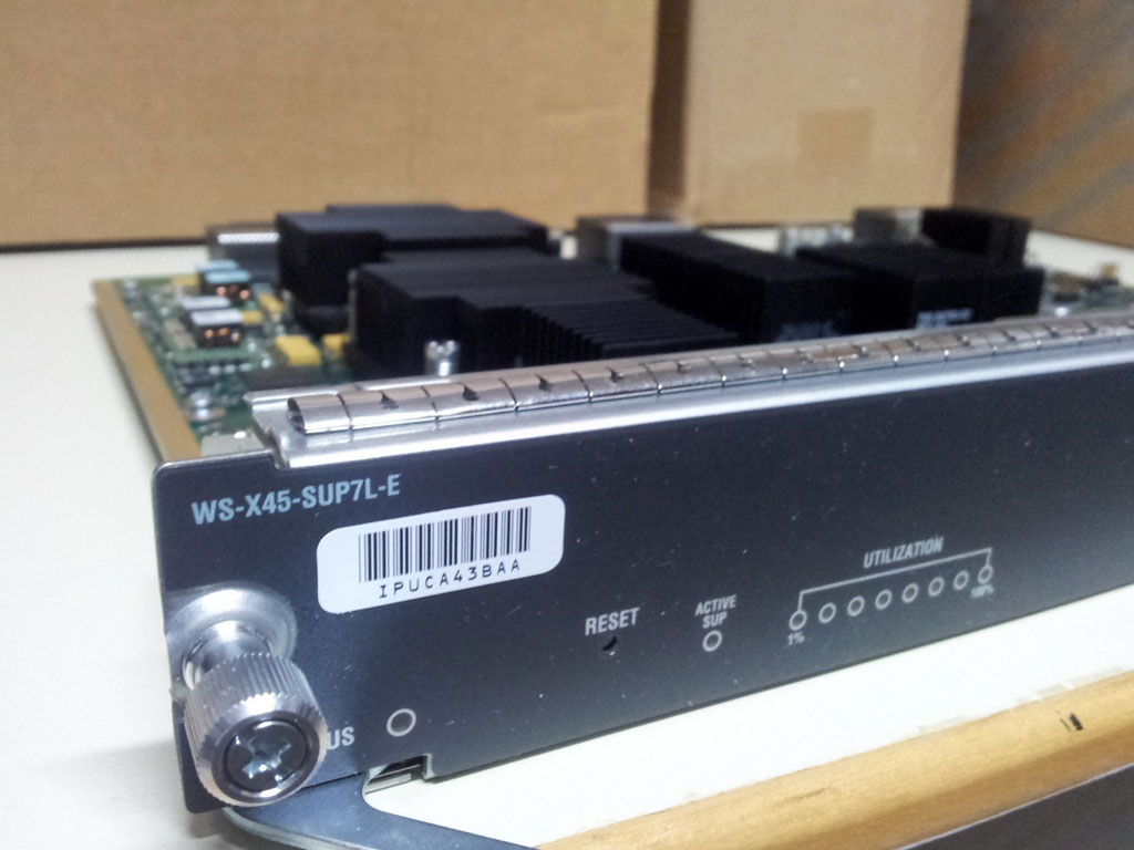
Looking to the front left side of the Supervisor Engine, we can see the Status LED, Active SUP LED (on when the Sup. Engine is in active state) and Utilization LEDs. Visible behind the faceplate is the circuitry board and heatsinks attached to the dual-CPUs and other processors.:
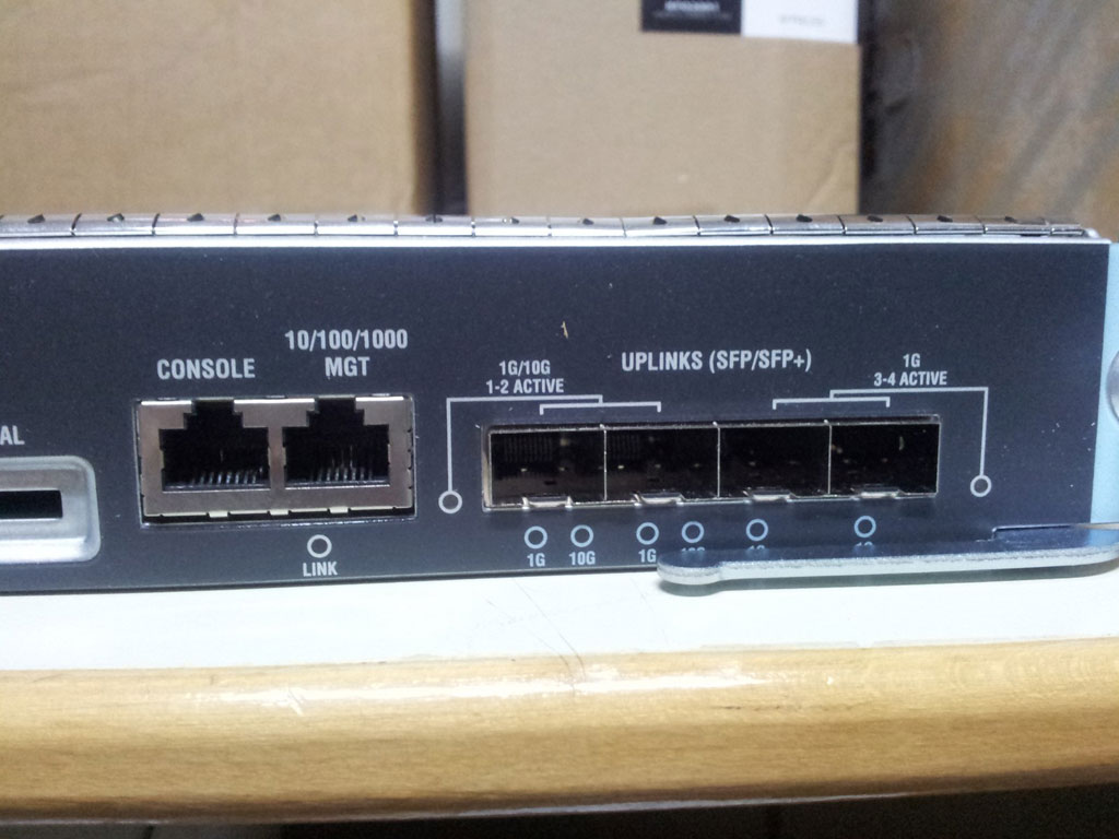
On the right we can see the Console port, Management port and 4 SFP/SFP+ slots providing two 10Gbps or four 1Gbps links! The LEDs below each SFP/SFP+ port will turn on according to the negotiated speed with the other end:
Looking at the back of the Supervisor Engine 7L-E, we can see the three connectors that plug directly into the 4507R+E chassis backplane. The heat sinks fins, covering the dual core CPU and other processors, are placed in a direction where the air from the fan tray can provide maximum cooling and heat dissipation:
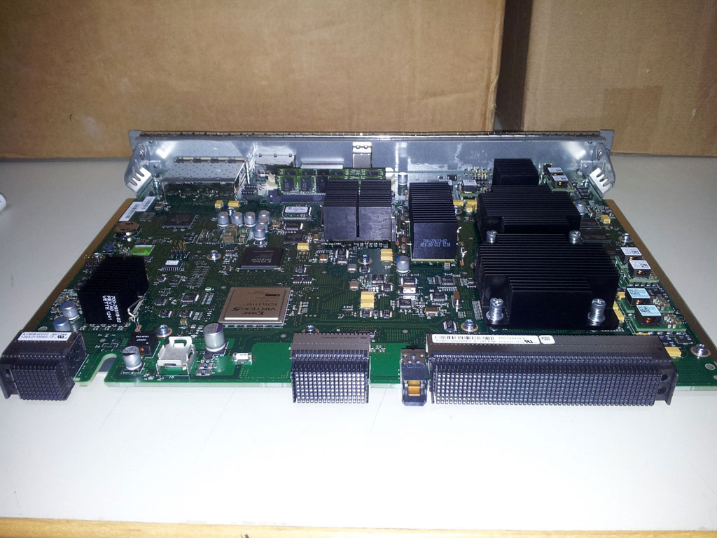
The Supervisor Engine 7L-E board is indeed impressive. The picture above shows the Supervisor Engine almost fully inserted into the 4507R+E chassis. We took this picture to show how the Supervisor Engine’s connectors perfectly line up with the 4507R’s backplane sockets:
Note how the Supervisor Engine’s processors carrying the large heatsinks are strategically placed next to the fan tray’s largest fans.
The WS-X4648-RJ45V+E Line Card
The WS-X4648-RJ45V+E line card provides a number of enhanced features designed to bring maximum flexibility and expandability some of which are:
- 48 ports
- 10/100/1000 module (RJ-45)
- Supported from Cisco IOS Software Release 12.2(40)SG or later
- IEEE 802.3af/at and Cisco prestandard PoE, IEEE 802.3x flow control
- Bandwidth is allocated across eight 6-port groups, providing 3 Gbps per port group (2:1)
- L2-4 Jumbo Frame support (up to 9216 bytes)
- Capable of up to 30 Watts of inline power per port on up to 24 ports simultaneously
- Enterprise and commercial: designed to power next-generation IP phones, wireless base stations, video cameras, and other PoE devices
- Campus and branch applications requiring enhanced performance for large file transfers and network backups
In the photo below, we can see the WS-X4648 main board with its chipsets, two of which are equipped with large heatsinks. The white connector at the back provides the connection with the 4507R+E backplane through which the card and its PoE ports are powered, and data traffic is carried to the rest of the system:
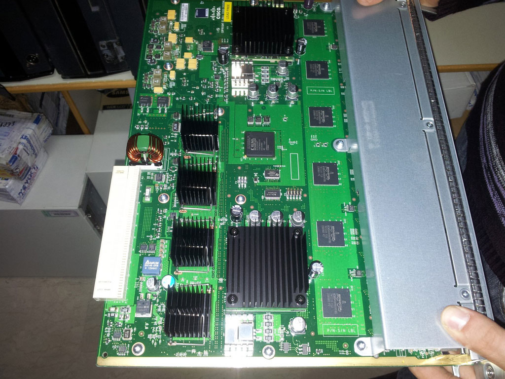
We should note that all 4500 & 6500 series line cards, including Supervisor Engines, have a metal carrier on the bottom of the board that covers almost all of the circuit board, making it safe to hold the line card without touching any circuits:
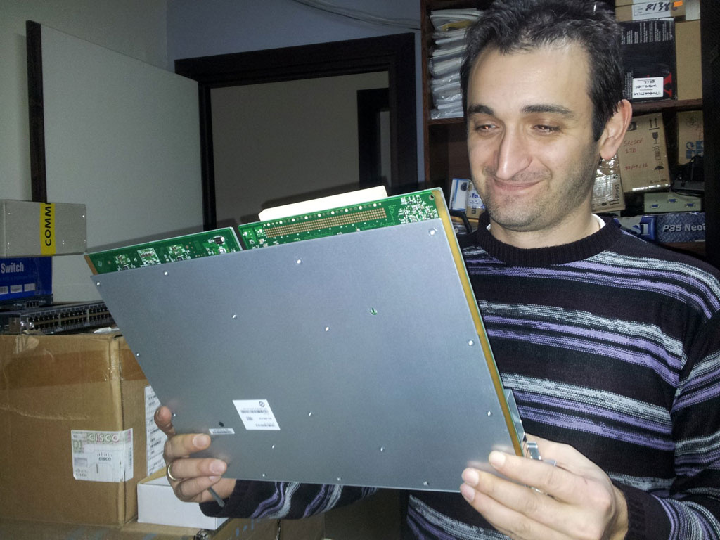
Network Administrator Savvas Filippidis gets ready to install a line card
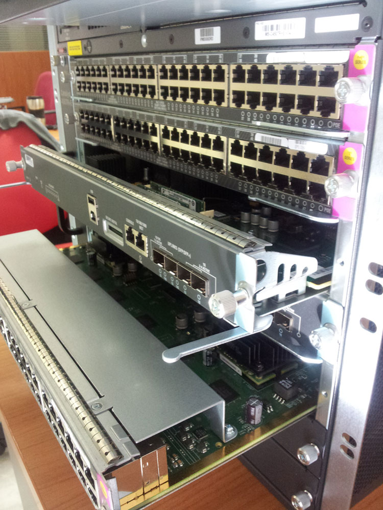
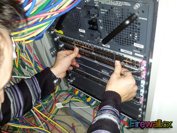
After a careful inspection of the card it was time to place it into its slot and complete the physical installation of the 4507R+E switch. After ensuring the two module ejector levers (one on each side) were out and away from the faceplate, we gently lined it up with the two chassis slot guides of our slot and slowly pushed the line card inwards:
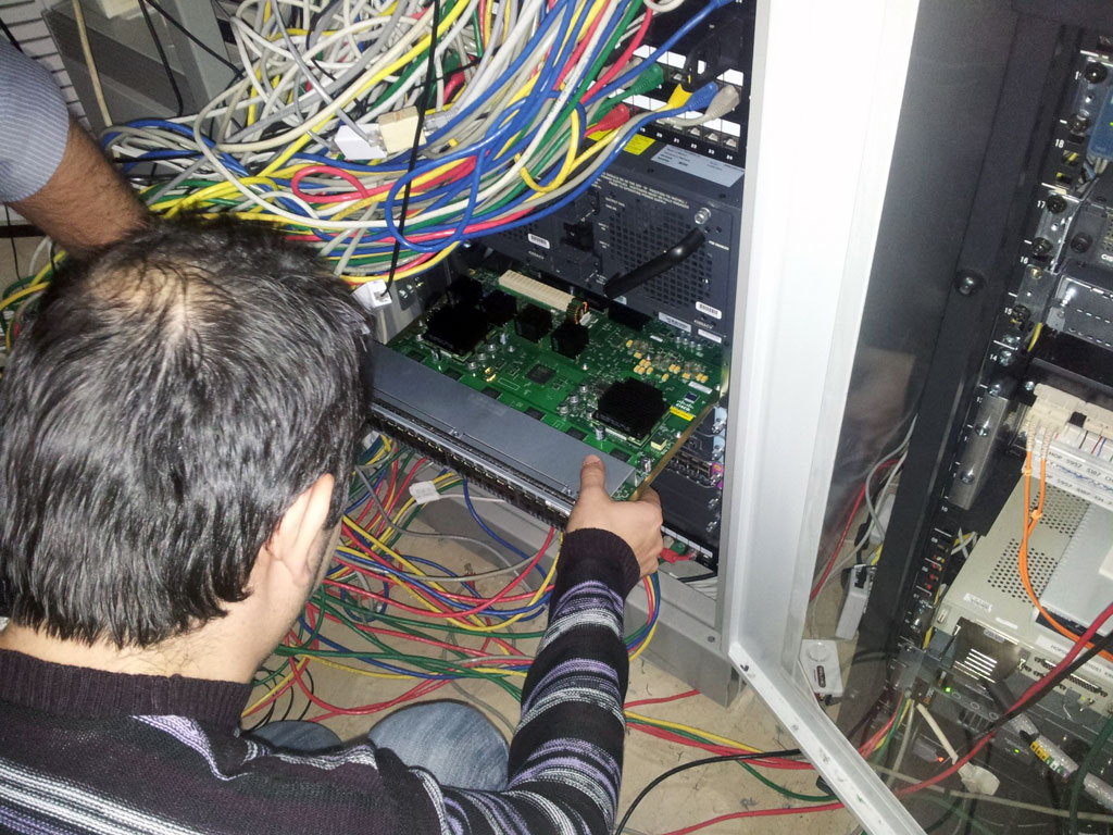
As soon as the line card’s connector ‘touched’ the backplane we continued to push it inwards, with a little more strength this time, and the two module ejector levers automatically started to fold inwards until the line card was fully in place:
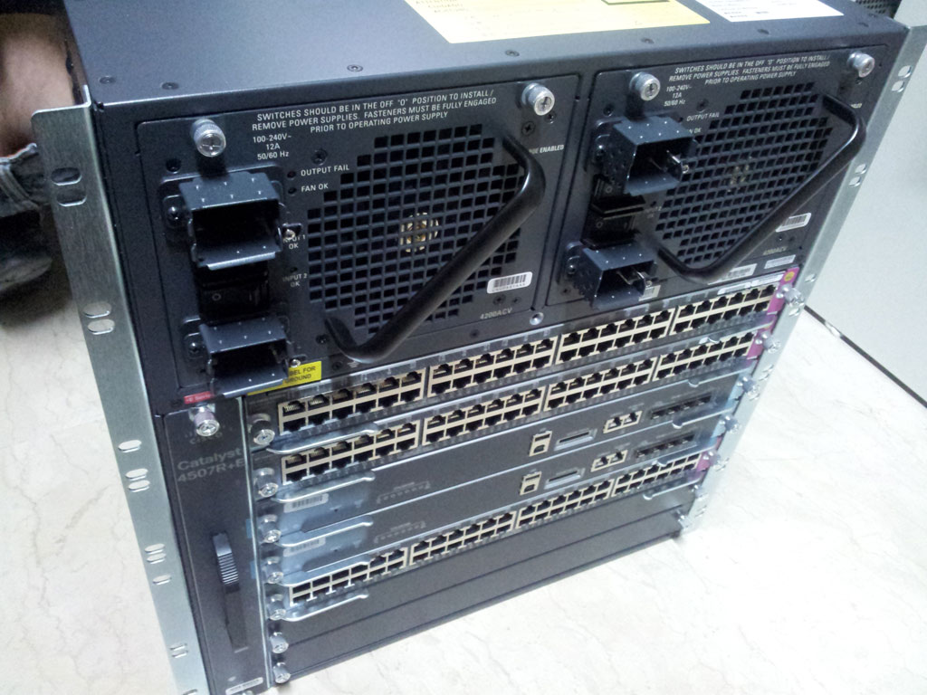
Cisco 4507R+E 4200Watt Power Supplies
The Cisco 4507R+E supports a number of different power supply configurations. Depending on how the switch is intended to be used, it can be populated fully with 48 Gigabit PoE ports, providing full PoE to all 5 line cards – a total of 240 ports where each line card can draw a maximum of 820 Watts.
Of course, the switch needs the appropriate power supplies to be able to undertake the load and this is why it’s always a great idea to purchase large power supplies as you’ll never need to upgrade them in the future when the switch is fully populated with PoE line cards.
The whopping 4200Watt power supplies were a considerable weight. To remove them, we had to loosen the captive installation screws (two for each power supply) and pull the power supply slowly outwards. Pulling out the power supply did not require much effort as it came out smoothly with the little force we used.
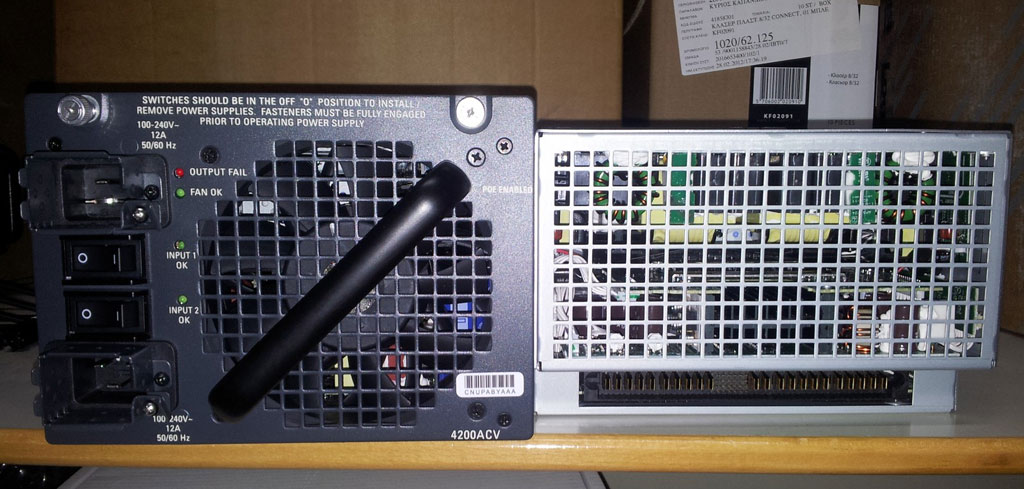
The 4200Watt power supply is the second largest power supply available for the 4500 series and has two IEC60320-C20 connectors (per power supply) to ensure the power drawn from the UPS or power circuit is evenly split.
We took both power supplies out and took a picture of them to show both front and back side. At the back of each power supply, as expected, we found one long connector, split into three groups, the middle group containing pins which are barely visible in the picture:
Going back to the chassis, all we found was the power supply connector where the middle pin sockets are easily seen. In total we counted an impressive 46 connection points between the power supply and chassis:
When we initially powered the Cisco 4507R+E switch, after it booted up we found both Supervisor Engine Status LEDs orange. After checking Cisco's site to find out more information, the explanation for the orange LEDs was that the Supervisor Engine was performing a 'System boot or a diagnostic test is in progress', however it was not true as the system was fully booted and working. A careful inspection showed that we had forgotten to switch on the second 4200Watt power supply and the system was running off only one power supply. At the time, the power requirements were only around 500Watts and the system was reporting the second power supply as "bad/off".
As soon as we switched on the second power supply, the Supervisor Engine LEDs magically turned Green! While we found no documentation to explain this behavior, we thought it would be worth mentioning for our readers and engineers preparing to install a 4500 series switch!
Article Conclusion
Those who have had the luck to physically install and work on a Cisco Catalyst 4507R or any Catalyst 4500 series switch would surely agree that it is a wonderful experience and impressive piece of equipment. Examining the design and construction of the chassis, line cards and Supervisor Engines shows how much thought and work have gone into the product.
Our next article covers the IOS upgrade of the Supervisor engine, health checkup, using the zero downtime IOS upgrade procedure – a necessary and extremely handy procedure that ensures the upgrade of the IOS Supervisor engines without any service interruption! Read it Now!
For a complete list of our article, readers can visit www.Firewall.cx.
Find answers to your questions by entering keywords or phrases in the Search bar above. New here? Use these resources to familiarize yourself with the community: