- Cisco Community
- Technology and Support
- Networking
- Switching
- Can this be done without
- Subscribe to RSS Feed
- Mark Topic as New
- Mark Topic as Read
- Float this Topic for Current User
- Bookmark
- Subscribe
- Mute
- Printer Friendly Page
- Mark as New
- Bookmark
- Subscribe
- Mute
- Subscribe to RSS Feed
- Permalink
- Report Inappropriate Content
04-19-2017 09:54 PM - edited 03-08-2019 10:15 AM
Hello,
One of the vlans - vlan 51 needs to be spanned.
SVI for vlan 51 is configured on the layer 3 switch whereas the users in this vlan are on another layer 2 switch.
which will be a good place to span traffic for this vlan & what configuration can be used.
Thanks in advance.
Solved! Go to Solution.
- Labels:
-
LAN Switching
Accepted Solutions
")
")
- Mark as New
- Bookmark
- Subscribe
- Mute
- Subscribe to RSS Feed
- Permalink
- Report Inappropriate Content
05-03-2017 01:20 AM
Hi
then you could do an remote span RSPAN instead of a local SPAN and collect all the info from vlan 51 users on other switches
This doc shows how to set it up
http://www.cisco.com/c/en/us/td/docs/switches/lan/catalyst2960/software/release/12-2_40_se/configuration/guide/scg/swspan.pdf
- Mark as New
- Bookmark
- Subscribe
- Mute
- Subscribe to RSS Feed
- Permalink
- Report Inappropriate Content
04-20-2017 12:49 AM
When you say 'spanned', presumably you mean made available for use on another switch?
If so, you simply need an 802.1q Trunk port between your Layer 3 Switch and your Layer 2 switch.
The fact your switch is Layer 3 capable is irrelevant, it still functions as a standard Layer 2 switch in terms of the Vlans.
Create Vlan 51 as a L2 Vlan on the other switch and configure an 802.1q Trunk between the switches.
It should work fine.
Thanks
- Mark as New
- Bookmark
- Subscribe
- Mute
- Subscribe to RSS Feed
- Permalink
- Report Inappropriate Content
04-20-2017 12:54 AM
Hi you can just push it out its a layer 2 vlan don th trunk link to the switch if that's what you mean by span it
1 make sure the vlan is created at layer 2 on both switches, it should already be on l3 switch as SVI there , show vlan
vlan 51
name xxxxx
2 make sure both sides of the trunk are allowing vlan 51 , example
interface GigabitEthernet1/0/7
description xxxxxxxxxxxxx
switchport trunk allowed vlan 51
switchport mode trunk
mls qos trust dscp
spanning-tree portfast trunk
3 make sure the users in the layer 2 switch can ping the vlan interface 51 on the layer 3 switch and they should be good to go , whether dhcp assigned or static
Or do you mean actual SPAN monitor collect the user vlan info , if so this on the l2 switch
set destination port connect pc to it with wireshark running
monitor session 2 destination interface g1/0/1
monitor session 2 source vlan 51
- Mark as New
- Bookmark
- Subscribe
- Mute
- Subscribe to RSS Feed
- Permalink
- Report Inappropriate Content
04-20-2017 04:02 PM
Thank you for the reply.
Apologies, for not clearly mentioning the question.
Yes, it is about SPAN monitoring vlan 51 for checking out user info.
Will it be better to put the span on layer 2 switch where users are actually connected or the L3 where the actual SVI for vlan 51 sits.
")
")
- Mark as New
- Bookmark
- Subscribe
- Mute
- Subscribe to RSS Feed
- Permalink
- Report Inappropriate Content
04-20-2017 04:29 PM
Hi
It depends where is located the destination port, if it is on the layer 3 switch you could configure the normal remote span on it or use RSPAN on the layer 2 and 3 otherwise the normal span session can be configured on the Layer 2 switch, you can specify the vlan to monitor or the interfaces.
http://www.networkstraining.com/how-to-configure-cisco-span-rspan-erspan/
Hope it is useful
:-)
>> Marcar como útil o contestado, si la respuesta resolvió la duda, esto ayuda a futuras consultas de otros miembros de la comunidad. <<
- Mark as New
- Bookmark
- Subscribe
- Mute
- Subscribe to RSS Feed
- Permalink
- Report Inappropriate Content
04-20-2017 04:58 PM
Thanks.
The source users (multiple on vlan 51) are on a layer 2 switch. SVI for it is on another layer 3 switch.
basically, we need to be able to look at the packets right from bootup process when users turn on the pc & gain connectivity. Won't this be better achieved by using SPAN on layer 2 switch itself so the traffic doesn't have to go over this particular l2 switch, just to avoid any unforeseen issues during capture.
Or will it be more beneficial to do SPAN on layer 3 where the SVI resides?
Sorry, but i am just trying to see which is the best portion to do so.
- Mark as New
- Bookmark
- Subscribe
- Mute
- Subscribe to RSS Feed
- Permalink
- Report Inappropriate Content
04-21-2017 12:31 AM
Hi
as I understad your topology it would be best for you to do the SPAN session on layer 2 switch, closer to your PC's. Just make on L2 switch the Vlan as source and a physical interface as destination.
- Mark as New
- Bookmark
- Subscribe
- Mute
- Subscribe to RSS Feed
- Permalink
- Report Inappropriate Content
04-24-2017 07:49 AM
Thanks for that.
Once the configuration is done, when i plug my pc into the destination port how should i ensure the wireshark on my PC is actually getting the data?
Is there any settings on the wireshark to be done..i am not sure but i think the nic adapter which connects to the switch port will need to be selected in wireshark or so?
please suggest.
- Mark as New
- Bookmark
- Subscribe
- Mute
- Subscribe to RSS Feed
- Permalink
- Report Inappropriate Content
04-24-2017 08:07 AM
i am not sure but i think the nic adapter which connects to the switch port will need to be selected in wireshark or so?
exactly that on the wirehsark GUI you pick your adapter that's connected , then hit start your port will be up/down monitoring on the switch and then you will see a flood of traffic coming into wireshark arp/dns etc whatevers on the wire as your doing it
quick video may help
https://www.youtube.com/watch?v=af4d_fAkwAY
- Mark as New
- Bookmark
- Subscribe
- Mute
- Subscribe to RSS Feed
- Permalink
- Report Inappropriate Content
05-02-2017 08:52 PM
If the users on vlan 51 are connected across multiple layer 2 switches, will it be advisable to do this sniff on the layer 3 switch which holds vlan 51's SVI?
We need to see all the users packets starting from booting up for this particular vlan 51. Unfortunately, the users in this vlan are spread across multiple switches.
Appreciate all reply.
- Mark as New
- Bookmark
- Subscribe
- Mute
- Subscribe to RSS Feed
- Permalink
- Report Inappropriate Content
05-03-2017 01:20 AM
Hi
then you could do an remote span RSPAN instead of a local SPAN and collect all the info from vlan 51 users on other switches
This doc shows how to set it up
http://www.cisco.com/c/en/us/td/docs/switches/lan/catalyst2960/software/release/12-2_40_se/configuration/guide/scg/swspan.pdf
- Mark as New
- Bookmark
- Subscribe
- Mute
- Subscribe to RSS Feed
- Permalink
- Report Inappropriate Content
05-03-2017 07:50 PM
Can this be done without RSPAN. If the machine with sniffer is connected on the same L3 switch where vlan 51 SVI is, will all the packets for vlan 51 be not available to the sniffer?
- Mark as New
- Bookmark
- Subscribe
- Mute
- Subscribe to RSS Feed
- Permalink
- Report Inappropriate Content
05-04-2017 12:16 AM
you have 3 types of span you can use , if your source span is on a different switch to the destination span it would need to be rspan across layer 2 or erspan across layer 3 links if it was ip based , local span source and destination needs to be local to the switch , rspan is the way to go here I don't know another way of collecting multiple switch spans unless you had an ANUE device or some other special traffic monitoring device on the LAN
http://www.cisco.com/c/en/us/td/docs/switches/lan/catalyst6500/ios/12-2SX/configuration/guide/book/span.html
A local SPAN session is an association of source ports and source VLANs with one or more destinations. You configure a local SPAN session on a single switch. Local SPAN does not have separate source and destination sessions.
Local SPAN sessions do not copy locally sourced RSPAN VLAN traffic from source trunk ports that carry RSPAN VLANs. Local SPAN sessions do not copy locally sourced RSPAN GRE-encapsulated traffic from source ports.
Each local SPAN session can have either ports or VLANs as sources, but not both.
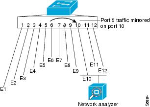
Local SPAN copies traffic from one or more source ports in any VLAN or from one or more VLANs to a destination for analysis (see Figure 68-1). For example, as shown in Figure 68-1, all traffic on Ethernet port 5 (the source port) is copied to Ethernet port 10. A network analyzer on Ethernet port 10 receives all traffic from Ethernet port 5 without being physically attached to Ethernet port 5.
Figure 68-1 Example SPAN Configuration
RSPAN Overview
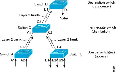
RSPAN supports source ports, source VLANs, and destinations on different switches, which provides remote monitoring of multiple switches across your network (see Figure 68-2). RSPAN uses a Layer 2 VLAN to carry SPAN traffic between switches.
RSPAN consists of an RSPAN source session, an RSPAN VLAN, and an RSPAN destination session. You separately configure RSPAN source sessions and destination sessions on different switches. To configure an RSPAN source session on one switch, you associate a set of source ports or VLANs with an RSPAN VLAN. To configure an RSPAN destination session on another switch, you associate the destinations with the RSPAN VLAN.
The traffic for each RSPAN session is carried as Layer 2 nonroutable traffic over a user-specified RSPAN VLAN that is dedicated for that RSPAN session in all participating switches. All participating switches must be trunk-connected at Layer 2.
RSPAN source sessions do not copy locally sourced RSPAN VLAN traffic from source trunk ports that carry RSPAN VLANs. RSPAN source sessions do not copy locally sourced RSPAN GRE-encapsulated traffic from source ports.
Each RSPAN source session can have either ports or VLANs as sources, but not both.
The RSPAN source session copies traffic from the source ports or source VLANs and switches the traffic over the RSPAN VLAN to the RSPAN destination session. The RSPAN destination session switches the traffic to the destinations.
Figure 68-2 RSPAN Configuration
ERSPAN Overview
ERSPAN supports source ports, source VLANs, and destinations on different switches, which provides remote monitoring of multiple switches across your network (see Figure 68-3). ERSPAN uses a GRE tunnel to carry traffic between switches.
ERSPAN consists of an ERSPAN source session, routable ERSPAN GRE-encapsulated traffic, and an ERSPAN destination session. You separately configure ERSPAN source sessions and destination sessions on different switches.
To configure an ERSPAN source session on one switch, you associate a set of source ports or VLANs with a destination IP address, ERSPAN ID number, and optionally with a VRF name. To configure an ERSPAN destination session on another switch, you associate the destinations with the source IP address, ERSPAN ID number, and optionally with a VRF name.
ERSPAN source sessions do not copy locally sourced RSPAN VLAN traffic from source trunk ports that carry RSPAN VLANs. ERSPAN source sessions do not copy locally sourced ERSPAN GRE-encapsulated traffic from source ports.
Each ERSPAN source session can have either ports or VLANs as sources, but not both.
The ERSPAN source session copies traffic from the source ports or source VLANs and forwards the traffic using routable GRE-encapsulated packets to the ERSPAN destination session. The ERSPAN destination session switches the traffic to the destinations.
Find answers to your questions by entering keywords or phrases in the Search bar above. New here? Use these resources to familiarize yourself with the community:
