- Cisco Community
- Technology and Support
- Networking
- Networking Knowledge Base
- How to use Time-Domain Reflectometer (TDR)
- Subscribe to RSS Feed
- Mark as New
- Mark as Read
- Bookmark
- Subscribe
- Printer Friendly Page
- Report Inappropriate Content
- Subscribe to RSS Feed
- Mark as New
- Mark as Read
- Bookmark
- Subscribe
- Printer Friendly Page
- Report Inappropriate Content
10-11-2011 02:57 PM - edited 08-24-2023 05:01 PM
I’m no electrical engineer, (the closest experience I have with electricity is the amount of electrocution I received when I was a child [due to faulty cabling of electrical appliances]) so I will spare readers technical jargons and boring formulas because this guide is not aimed to be published in the International Journal of Mumbo-Jumbo. This guide is to help anyone how to confidently use the TDR feature when troubleshooting basic Layer 1 Ethernet issue.
My knowledge with this feature is based entirely on experience and a lot of trial-and-error.
What is Time-Domain Reflectometer (TDR)?
“A time-domain reflectometer (TDR) is an electronic instrument used to characterize and locate faults in metallic cables (for example, twisted wire pairs, coaxial cables)1.”
For the sake of this document, “TDR testing” and “TDR” are used interchangeably to sow confusion to the un-initiated. They both mean the same.
How can TDR help me?
TDR, in its simplest form, can help you determine IF you have a cable problem, WHICH pair(s) is/are faulty and HOW FAR away the fault is.
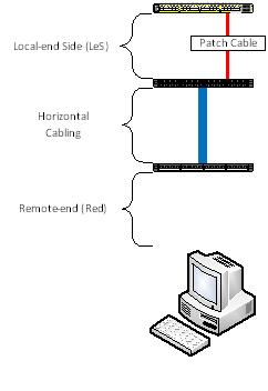
Typically, when you have a Layer 1 issue there are a lot of factors to consider:
- Local-end Side (LeS) patch cable;
- Local-end Side (LeS) patch panel (including punch block);
- Horizontal cable;
- Remote-end (Red) patch panel (including punch block);
- Remote-end (Red) patch cable; and
- Remote-end (Red) device NIC
So you see, dear readers, TDR minimize the guess-work.
Picture this …
Before we begin, let me give you the “lay of the land”. Presume the following scenario:

What model of Cisco switch does TDR work on?
Firstly, not all switch model support TDR. TDR feature first came out with the Catalyst 2960. So here is the list of which ones will work and will not:
|
Model |
TDR Support |
|
2960 |
Yes1, 2 |
|
2960G |
Yes |
|
2960S |
Yes |
|
2918 |
Unknown |
|
2350 |
Unknown |
|
2360 |
Unknown |
|
2975 |
Unknown |
|
3560 |
No |
|
3560G |
Yes |
|
3560E/3560X |
Yes |
|
3750 |
No |
|
3750G |
Yes |
|
3750E/3750X |
Yes |
|
Nexus 2K |
Unknown |
|
Nexus 5K |
Unknown |
|
Nexus 7K |
Yes3 |
|
Sup7E/X4548 |
Yes |
Note:
- 1. The 2960 will support TDR in both the FastEthernet and dual-personality GigiabitEthernet port, however, when used on a FastEthernet port, TDR will only test the first two pairs, namely Pairs A & B. For obvious reasons, Pairs C and D will not be tested when used on non-GigabitEthernet ports.
- 2. Except the WS-C2960-48PDL, when using the copper GigabitEthernet port of the Catalyst 2960, one must manually set the interface to copper using the command “media rj” before the test can be conducted.
- 3. Confirmed by Cisco TAC, Ankur Garg.
The list does not include modules/blades for the Catalyst 4000/4500, 5000/5500, 6000/6500 although it is mentioned here that TDR was introduced with IOS Release 12.2 ZY for the Catalyst 6000/6500. It’s not included in the list above because I don’t have the resources to test and verify.
Legacy Cisco Catalyst models 1900, 2900XL/3500XL, 2940/2950/2955, 2948G and 2970 are not supported. Routers are also not supported. I do not have any resources to test router Ethernet Switch Modules (NME, HWIC, EHWIC). Wireless Access Points do not support TDR.
Why doesn’t the FastEthernet-flavoured 3560 and 3750 support TDR and but the cheaper FastEthernet 2960 support TDR?
Base on the time-line, the “plain” (or non-GigabitEthernet copper port) 3560 and 3750 came out BEFORE the 2960. The “chip” for the TDR was included in the design of the 2960. When Cisco released the 3560G and 3750G later, someone made the ultimate decision to include the TDR feature as a standard. Therefore, the plain 3560 and 3750 are the only two series that WON’T HAVE the TDR feature. (Take note reader: Emphasis on the words “WON’T HAVE”)
Any Gotchas I need to be aware of?
- Switches need to run IOS version 12.2 or later. TDR is supported in IOS version 15.0. IOS version 12.0 and 12.1 do NOT support TDR.
- If you are running IOS version 12.2(46)SE or earlier, TDR test is DISRUPTIVE. During the test, the interface will go down and up. For obvious reasons, anything connected will lose network connectivity.
- If the remote-end device is a power-over-ethernet (PoE) device, the test will cause the device to lose power. If you have, for example, a Voice over IP (VoIP) phone and a PC client is connected to the phone, both the phone and client will lose network connectivity because the phone does not have a bypass functionality. This will affect ALL IOS versions.
- Particularly when you are running old IOS versions, the test can take between five (5) to seven (7) seconds.
- TDR works on 10/100/1000BaseTx. Fibre optic ports (any flavours) is not covered/discussed here. TenGigabitEthernet copper port DOES NOT (YET) support TDR.
- Cisco GLC-T/GLC-TX SFP module does NOT support TDR.
The next two Gotcha items are for those who plan to use the TDR feature on Cisco Catalyst 2960 and 2960G (2960S not included):
- 1. The 2960 will support TDR in both the FastEthernet and dual-personality GigiabitEthernet port, however, when used on a FastEthernet port, TDR will only test the first two pairs, namely Pairs A & B. For obvious reasons, Pairs C and D will not be tested when used on non-GigabitEthernet ports. Pairs C and D will report a result of “Not Supported”.
- 2. Except the WS-C2960-48PDL, when using the copper GigabitEthernet (Gig 0/1 and Gig 0/2) ports of the Catalyst 2960, one must manually set the interface to copper using the command “media rj” before the test can be conducted.
How to use TDR?
The commands are very simple: One to start the test and the second command to display the result. Here is simple procedure:
- Command to start the TDR: “test cable tdr interface <interface of your choice>”;
- Wait for about 5 to 7 seconds for the test to run; and
- Command to show the result of the TDR test: “show cable tdr interface <interface of your choice>”
See? Easy! Now let’s see what the I results would look like.
|
Interface |
Speed |
Local pair |
Pair length |
Remote pair |
Pair status |
|
Gi0/1 |
1000M |
Pair A |
3 +/- 1 meters |
Pair A |
Normal |
|
Pair B |
3 +/- 1 meters |
Pair B |
Normal |
||
|
Pair C |
3 +/- 1 meters |
Pair C |
Normal |
||
|
Pair D |
3 +/- 1 meters |
Pair D |
Normal |
So what does this result above tell us?
- Port tested is on GigabitEthernet 0/1;
- Port has negotiated to 1 Gbps;
- Cable use is a straight-through cable (look and compare the values of “Local pair” and “remote pair”);
- Cable length is approximately 3 metres long and an error (length-wise) of 1 metre; and
- All four pairs are working fine (Pair status)
Under “Pair status” you can get the following results:
|
Result |
Explaination |
|
Normal |
Ideal result you want.
|
|
Open |
Open circuit. This means that one (or more) pair has “no pin contact”. |
|
Short |
Short circuit. |
|
Impedance Mismatched |
Bad cable. For more explanation, go here. |
An ideal result is “Normal”. In practice, whether the remote-end device is FastEthernet or GigabitEthernet, I will never accept a TDR result other than “Normal” in all four pairs.
Cable Pairs explained?
This is how I see what each Pairs control:
|
Pairs |
Function |
|
A |
This pair controls whether or not the port should go up or down. |
|
B |
Protocol-level and controls FastEthernet. |
|
C |
Power over Ethernet (PoE) |
|
D |
GigabitEthernet |
More examples
|
Interface |
Speed |
Local pair |
Pair length |
Remote pair |
Pair status |
|
Gi0/11 |
100M |
Pair A |
13 +/- 1 meters |
Pair B |
Normal |
|
Pair B |
12 +/- 1 meters |
Pair A |
Normal |
||
|
Pair C |
0 +/- 1 meters |
Pair D |
Open |
||
|
Pair D |
0 +/- 1 meters |
Pair C |
Open |
Normally, this result would freak me out. Look at the items in RED. Pairs C and D are reporting a cable value of “0”. Next I move to the “Pair status” and it’s reported as an Open circuit. No pin contact. Whao! But look at the speed. It’s 100 Mbps. So it’s normal … I guess.
But wait. What if the remote-end side (Red) client is a GigabitEthernet. So where is the faulty cabling? Which one of the patch cables? Or is it a horizontal cabling? Does the client support GigabitEthernet or not?
Here’s another clue: Look at the length of the cable for Pair A and B. It’s reporting around 12 to 13 metres. Experience has taught me that my Local-end Side (LeS) cable doesn’t exceed two metres. So that rules out my cable, however the horizontal cabling is more than 10 metres. So what’s between the horizontal cabling and the remote-end client? You have three suspects: 1) The remote-end punch block; 2) the remote-end patch cable; and 3) remote-end client.
Culprit was the remote-end punch block and the horizontal cabling: Cable contractors only terminated two pairs.
Never ask a boy to do a man’s job!
|
Interface |
Speed |
Local pair |
Pair length |
Remote pair |
Pair status |
|
Gi1/0/48 |
auto |
Pair A |
149 +/- 1 meters |
Pair B |
Normal |
|
Pair B |
151 +/- 1 meters |
Pair A |
Normal |
||
|
Pair C |
35 +/- 1 meters |
Pair D |
Short/Impedance Mism |
||
|
Pair D |
21 +/- 1 meters |
Pair C |
Short/Impedance Mism |
Its results like the ones above that makes me want to cry.
Ok, I look under “Pair status” and I see “Short/Impedance Mism” for Pair C and D. No question about it. It’s bad cabling. This is not what makes me want to cry. Look at under “Pair length” of Pair A and B. NOW cry.
Should I be worried?
|
Interface |
Speed |
Local pair |
Pair length |
Remote pair |
Pair status |
|
Fa0/39 |
100M |
Pair A |
6 +/- 1 meters |
N/A |
Open |
|
Pair B |
49 +/- 1 meters |
N/A |
Open |
||
|
Pair C |
N/A |
N/A |
Not Supported |
||
|
Pair D |
N/A |
N/A |
Not Supported |
Looking at the result, I can confidently say that the appliance was a 48-port Cisco Catalyst 2960. How? Look under “Interface”. Look at “Pair status” for Pair C and D. Only the plain 2960 FastEthernet ports can support TDR.
But look at “Pair status” for Pairs A and B. What does that mean?
It means that the remote-end (Red) patch cable is missing.
Weird things have happened before
I’ve taken the opportunity to do limited testing on TDR on a 4510R+E. The chassis has a Sup7E and with a X4548-RJ45V+ line card (IOS version 03.01.01.SG). The result(s) are very, very weird. Oh, by the way, the TDR testing on this setup takes 60 seconds. 60 seconds! Good grief! I have no idea whether the Sup7E or the line card is the factor.
The sample below is coming from a GOOD cable:
|
Interface |
Speed |
Local pair |
Pair length |
Remote pair |
Pair status |
|
Gi2/36 |
1Gbps |
1-2 |
29 +/-10m |
Unknown |
Fault |
|
3-6 |
30 +/-10m |
Unknown |
Fault |
||
|
4-5 |
29 +/-10m |
Unknown |
Fault |
||
|
7-8 |
30 +/-10m |
Unknown |
Fault |
And the sample below is coming from a BAD cable:
|
Interface |
Speed |
Local pair |
Pair length |
Remote pair |
Pair status |
|
Gi2/37 |
0Mbps |
1-2 |
56 +/-10m |
Unknown |
Fault |
|
3-6 |
0 m |
Unknown |
Fault |
||
|
4-5 |
56 +/-10m |
Unknown |
Fault |
||
|
7-8 |
59 +/-10m |
Unknown |
Fault |
As you can see, whether or not you have a good or a bad cable the result from the “Remote pair” and “Status” can be deceiving. The ONLY WAY to determine if you have a bad cable issue or not is to look at the “Speed” and the output to the “Pair length”.
I am suspecting that the misleading result of the “Remote pair” and the “Pair status” is an IOS bug.
(25 August 2023) IMPORTANT ADDENDUM:
Starting with IOS-XE (aka Polaris) version 16.X.X (and later), TDR is completely broken. I strongly urge people to stop relying TDR results from Catalyst switches if platform is running 16.X.X (and later), 17.X.X (and later) because the result is neither accurate nor reliable. The Bug IDs are: CSCvw97924 & CSCwd97177
Screenshots (below) of broken TDR results:


-- END OF TRANSMISSION --
- Mark as Read
- Mark as New
- Bookmark
- Permalink
- Report Inappropriate Content
Just to be sure, a gigabit cable test between two switches would drop the connection too, yes?
Hi Ade,
Yes, the connection will drop because the TDR will drop the Pair "D" during the test.
- Mark as Read
- Mark as New
- Bookmark
- Permalink
- Report Inappropriate Content
OK that's good to know. One more question
Do all of the switches use the same TDR process? That is, if I buy the latest and greatest switch, will it have identical functionality to an older model? I ask, as I get more accurate results when a cable tester unit than with the switch.
Thanks
Ade
- Mark as Read
- Mark as New
- Bookmark
- Permalink
- Report Inappropriate Content
Do all of the switches use the same TDR process? That is, if I buy the latest and greatest switch, will it have identical functionality to an older model?
I like the TDR functionality of the 2960/2960G/2960S and the 3750G/3750E/3750X because it is FAST. You need to just wait for about 5 to 7 seconds. However, the TDR functionalilty of the 3560G/3560E/3560X takes 61 seconds.
Next, line cards. The line cards for the 4500 and the 6500 also takes 61 seconds, however, if you run the TDR on the supervisor card then it takes around 5 to 7 seconds once again.
Accuracy, I can't tell you how "accurate" they are because if you ran the same "test" commands on the same wire length, say, 10 times, you'll get different results.
The switch TDR is no way a full substitute to a full-blown TDR, like the Fluke DTX 1800. One thing that you can do with switch TDR that you can't do with, say, a Fluke DTX is doing the the TDR from the comfort of your chair.
The switch TDR is a way of "complimenting" and ease the troubleshooting of Layer 1.
- Mark as Read
- Mark as New
- Bookmark
- Permalink
- Report Inappropriate Content
Thanks for the confirming the TDR on the Nexus 7K. Document updated about Nexus 7K support.
(Does the 2K/5K support TDR too?)
I can confirm that the 5K supports the TDR command at least as early as 5.0(2), unfortunately all of our interfaces are 10G/fiber, so I cannot say how well it works - but the command is there. Great article by the way, thanks.
- Mark as Read
- Mark as New
- Bookmark
- Permalink
- Report Inappropriate Content
Thanks Martin.
I haven't had the chance to actually test the accuracy of the TDR on the Nexus.
- Mark as Read
- Mark as New
- Bookmark
- Permalink
- Report Inappropriate Content
Quick question. I love TDR and thank you for explaining it in depth, as it is not so simple as I might have assumed.
I have a 2960 switch showing a problem, but I am not sure which wire pair is pair A, B, C, D. I would assume A=1&2 B=3&6, C=4&5, and D=7&8 but I can't find any specifics in the documentation.
Your post shows output from multiple versions of IOS, which implies that I am correct. I'd just like to hear from someone that has tested with bad cables or see Cisco's documentation on this. If anyone can point me in the right direction, I would appreciate it.
I will try to come back and answer later if I find time get some equipment and test it myself.
- Mark as Read
- Mark as New
- Bookmark
- Permalink
- Report Inappropriate Content
I would assume A=1&2 B=3&6, C=4&5, and D=7&8 but I can't find any specifics in the documentation.
Your asumption is correct.
Your post shows output from multiple versions of IOS, which implies that I am correct. I'd just like to hear from someone that has tested with bad cables or see Cisco's documentation on this.
TDR in some IOS versions do not work (well). For instance, if you are using IOS version, 15.0(2)SE there's a bug when you run TDR it gets "stuck". Your "sh interface <BLAH>" will have an output like: <INTERFACE> is up, line protocol is up (connected: TDR running).
Unfortunately, TDR is not well documented because it ain't popular. You'll find a wealth of personal documentation outside.
- Mark as Read
- Mark as New
- Bookmark
- Permalink
- Report Inappropriate Content
Late last night I did get a 2960 and a cut cat5 cable. I can confidently tell you that the pairs are as mentioned previously. Good luck all! Happy cable testing!
- Mark as Read
- Mark as New
- Bookmark
- Permalink
- Report Inappropriate Content
Thanks for the feedback, Corey.
- Mark as Read
- Mark as New
- Bookmark
- Permalink
- Report Inappropriate Content
Nice one Dude.
- Mark as Read
- Mark as New
- Bookmark
- Permalink
- Report Inappropriate Content
Thanks Guru Dath.
- Mark as Read
- Mark as New
- Bookmark
- Permalink
- Report Inappropriate Content
Hi Leo. I need to get back on this...
In fact the situation where I get pairs A + B = normal and C + D = short could be interpreted as "the cable is ok, the connected device simply negotiates 100 Mbps"... is my assumption correct?
Thanks and regards,
Flavio.
- Mark as Read
- Mark as New
- Bookmark
- Permalink
- Report Inappropriate Content
Hi Flavio,
Your assumption and understanding is correct: The downstream client will ONLY negotiate to 10- or 100 Mbps. If you plug a power end device, like an IP Phone or wireless access point, then it won't work.
- Mark as Read
- Mark as New
- Bookmark
- Permalink
- Report Inappropriate Content
Hi Leo, thanks for your feedback.
Now it looks like this on a couple of ports on a C3850 with the latest 3.3.2 IOS on it:
vxs12a1#sh cable-diagnostics tdr int gi1/0/45
TDR test last run on: February 27 17:23:19
Interface Speed Local pair Pair length Remote pair Pair status
--------- ----- ---------- ------------------ ----------- --------------------
Gi1/0/45 auto Pair A 124 +/- 1 meters N/A Normal
Pair B 124 +/- 1 meters N/A Normal
Pair C 27 +/- 1 meters N/A Short
Pair D 29 +/- 1 meters N/A Short
vxs12a1#sh cable-diagnostics tdr int gi2/0/3
TDR test last run on: February 27 17:23:24
Interface Speed Local pair Pair length Remote pair Pair status
--------- ----- ---------- ------------------ ----------- --------------------
Gi2/0/3 auto Pair A 127 +/- 1 meters N/A Normal
Pair B 127 +/- 1 meters N/A Normal
Pair C 24 +/- 1 meters N/A Short
Pair D 26 +/- 1 meters N/A Short
vxs12a1#sh cable-diagnostics tdr int gi1/0/9
TDR test last run on: February 27 17:23:28
Interface Speed Local pair Pair length Remote pair Pair status
--------- ----- ---------- ------------------ ----------- --------------------
Gi1/0/9 auto Pair A 69 +/- 1 meters N/A Normal
Pair B 69 +/- 1 meters N/A Normal
Pair C 46 +/- 1 meters N/A Short
Pair D 47 +/- 1 meters N/A Short
vxs12a1#sh cable-diagnostics tdr int gi2/0/17
TDR test last run on: February 27 17:23:32
Interface Speed Local pair Pair length Remote pair Pair status
--------- ----- ---------- ------------------ ----------- --------------------
Gi2/0/17 auto Pair A 70 +/- 1 meters N/A Normal
Pair B 70 +/- 1 meters N/A Normal
Pair C 39 +/- 1 meters N/A Short
Pair D 41 +/- 1 meters N/A Short
vxs12a1#sh cable-diagnostics tdr int gi1/0/44
TDR test last run on: February 27 17:23:36
Interface Speed Local pair Pair length Remote pair Pair status
--------- ----- ---------- ------------------ ----------- --------------------
Gi1/0/44 auto Pair A 123 +/- 1 meters N/A Normal
Pair B 65535 +/- 1 meters N/A Not Supported
Pair C 27 +/- 1 meters N/A Short
Pair D 29 +/- 1 meters N/A Short
vxs12a1#sh cable-diagnostics tdr int gi2/0/42
TDR test last run on: February 27 17:23:40
Interface Speed Local pair Pair length Remote pair Pair status
--------- ----- ---------- ------------------ ----------- --------------------
Gi2/0/42 auto Pair A 69 +/- 1 meters N/A Normal
Pair B 69 +/- 1 meters N/A Normal
Pair C 46 +/- 1 meters N/A Short
Pair D 48 +/- 1 meters N/A Short
I measured above ports, because the logs tell me that
025116: Feb 27 17:00:12: %ILPOWER-3-CONTROLLER_PORT_ERR: Controller port error, Interface Gi1/0/45: Power Controller reports Short detected
for each of the above ports.
At the time I did the TDR, all above ports were "notconnected"... and the weird one with 65535 meters???
Thanks for your thoughts/suggestions on this one...
Regards,
Flavio.
- Mark as Read
- Mark as New
- Bookmark
- Permalink
- Report Inappropriate Content
The output for Gi 1/0/44 could be faulty. I've seen a case like and I immediately knew it was due to a faulty cable.
Gi 1/0/45 and Gi 2/0/3 both have a distance of >100 metres (Pair A & B). I am suspecting this is correct and you'll never get PoE with that distance. Look at the distance displayed for Pair C & D, they are almost similar. By this, I'd believe the values to be correct. You've got a bad cable and I think some of the wires were re-splice or you have a "consolidation point" somewhere between the back of the patch panel to the end of the line.
Look at the output to Gi 2/0/42 . Look at the distance to Pair C and Pair D. Again, the values look very similar to Gi 1/0/45 and Gi 2/0/3.
My recommendation is that you've got enough data to go back to your cable contractors and get them to re-test the lines affected. I would also recommend that you DO NOT accept form of "testing" unless the result comes from a Fluke DTX-1800 machine.
Find answers to your questions by entering keywords or phrases in the Search bar above. New here? Use these resources to familiarize yourself with the community: