- Cisco Community
- Technology and Support
- Networking
- Routing
- InterVlan routing from the client
- Subscribe to RSS Feed
- Mark Topic as New
- Mark Topic as Read
- Float this Topic for Current User
- Bookmark
- Subscribe
- Mute
- Printer Friendly Page
InterVlan routing from the client
- Mark as New
- Bookmark
- Subscribe
- Mute
- Subscribe to RSS Feed
- Permalink
- Report Inappropriate Content
02-08-2006 05:25 PM - edited 03-03-2019 11:41 AM
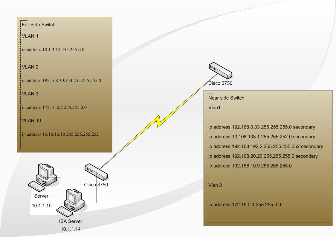
I have a Cisco 3750 connected to another Cisco 3750 via media converted fibre link.
Near side switch:
Current configuration : 2508 bytes
!
version 12.1
no service pad
service timestamps debug uptime
service timestamps log datetime
no service password-encryption
service sequence-numbers
!
hostname 3750
!
enable secret
enable password
!
ip subnet-zero
ip routing
!
ip host X 172.16.0.2
ip name-server 210.55.12.1
ip name-server 202.x.x.x
ip name-server 210.55.12.2
ip name-server 202.x.x.x
vtp mode transparent
cluster enable laptop 0
!
spanning-tree mode pvst
no spanning-tree optimize bpdu transmission
spanning-tree extend system-id
!
!
vlan access-map word 1
action forward
!
vlan 2
name vlan2
!
vlan 3
name 20subnet
!
vlan 4
!
interface GigabitEthernet1/0/1
!
interface GigabitEthernet1/0/2
!
interface GigabitEthernet1/0/3
!
interface GigabitEthernet1/0/4
!
interface GigabitEthernet1/0/5
!
interface GigabitEthernet1/0/6
!
interface GigabitEthernet1/0/7
!
interface GigabitEthernet1/0/8
!
interface GigabitEthernet1/0/9
!
interface GigabitEthernet1/0/10
!
interface GigabitEthernet1/0/11
!
interface GigabitEthernet1/0/12
!
interface GigabitEthernet1/0/13
!
interface GigabitEthernet1/0/14
!
interface GigabitEthernet1/0/15
duplex full
speed 10
!
interface GigabitEthernet1/0/16
!
interface GigabitEthernet1/0/17
!
interface GigabitEthernet1/0/18
!
interface GigabitEthernet1/0/19
!
interface GigabitEthernet1/0/20
!
interface GigabitEthernet1/0/21
switchport access vlan 2
switchport mode access
!
interface GigabitEthernet1/0/22
!
interface GigabitEthernet1/0/23
!
interface GigabitEthernet1/0/24
!
interface Vlan1
ip address 192.168.0.33 255.255.255.0 secondary
ip address 10.108.108.1 255.255.252.0 secondary
ip address 192.168.192.2 255.255.255.252 secondary
ip address 192.168.20.20 255.255.255.0 secondary
ip address 192.168.10.9 255.255.255.0
!
interface Vlan2
ip address 172.16.0.1 255.255.0.0
!
interface Vlan3
no ip address
!
ip classless
ip route 0.0.0.0 0.0.0.0 192.168.0.27
ip route 10.1.0.0 255.255.0.0 172.16.0.2
ip route 10.250.6.0 255.255.255.0 192.168.192.1
ip route 57.8.x.x.x.x.x.108.108.10
ip route 192.168.5.7 255.255.255.255 192.168.10.10
ip http server
!
ip access-list standard TEST10SUBNET
permit any
!
ip access-list extended CMP-NAT-ACL
dynamic Cluster-HSRP deny ip any any
dynamic Cluster-NAT permit ip any any
ip access-list extended TEST
permit ip any any
!
!
line con 0
line vty 0 4
password
login
line vty 5 15
password
login
!
end
We have created a seperate VLAN on both switches in order to set primary addresses of both on the 172.16.x.x network, and handle all routing internal to the switches. From the near side switch I am able to ping all remote networks.
On a host on VLAN1 on the near side switch, I can ping 172.16.0.1 which is an address on VLAN2 but not the far end of the fibre link or any other host on the far end of the link. If I trace to 172.16.0.1 it lists 1 hop directly to 172.16.0.1. If I trace to 172.16.0.2 I go to 192.168.10.9 and then the trace carries on for a few hops and gets lost. How can I get full transparency between networks?
- Labels:
-
Other Routing
- Mark as New
- Bookmark
- Subscribe
- Mute
- Subscribe to RSS Feed
- Permalink
- Report Inappropriate Content
02-08-2006 06:03 PM
Hi,
I would start by adding the following routes to the far side router:
ip route 192.168.0.33 255.255.255.0 172.16.0.1
ip route 10.108.108.1 255.255.252.0 172.16.0.1
ip route 192.168.192.2 255.255.255.252 172.16.0.1
ip route 192.168.20.20 255.255.255.0 172.16.0.1
ip route 192.168.10.9 255.255.255.0 172.16.0.1
Hope that helps - pls rate the post if it does.
Paresh
- Mark as New
- Bookmark
- Subscribe
- Mute
- Subscribe to RSS Feed
- Permalink
- Report Inappropriate Content
02-08-2006 06:07 PM
Actually, the above may or may not work.
Since you are using distinct subnets for each VLAN, I would suggest that you not use the same VLAN IDs on each side.. On the far side router, you should configure the 172.16.0.2 address under interface VLAN2. Remove the subnets from VLAN2 into a new VLAN. In addition, change VLAN1 to be some VLAN ID that you are not using elsewhere.
PAresh
- Mark as New
- Bookmark
- Subscribe
- Mute
- Subscribe to RSS Feed
- Permalink
- Report Inappropriate Content
02-08-2006 06:29 PM
Hi Paresh
Thanks for the prompt response.
Just for clarification:
Far side router is using 172.16.x.x in VLAN3. Near side router is using 172.16.x.x in VLAN2.
Why would I be able to ping 172.16.0.1 which is effectively in VLAN 2 on the near router from a host on the near routers VLAN 1 but nothing else.
Apparently far side router is able to ping 172.16.0.1 which is VLAN 2 on near router from a server 10.1.1.10 which is a far network!
Default gateway on remote network is set to an ISA box which is probably performing routing. No other layer device is available near side of the link.
Once again, thank you!
- Mark as New
- Bookmark
- Subscribe
- Mute
- Subscribe to RSS Feed
- Permalink
- Report Inappropriate Content
02-08-2006 06:34 PM
Answer to your first question: the switch knows exactly how to get to 172.16.0.1 since it's a directly connected address.
As for your second question, it's a bit hard to answer without understanding what the rest of your network looks like ... Have you got a network diagram you could post ?
Paresh
- Mark as New
- Bookmark
- Subscribe
- Mute
- Subscribe to RSS Feed
- Permalink
- Report Inappropriate Content
02-08-2006 06:57 PM
- Mark as New
- Bookmark
- Subscribe
- Mute
- Subscribe to RSS Feed
- Permalink
- Report Inappropriate Content
02-08-2006 07:01 PM
I'm afraid I'm not able to open that file.. it seems to be referencing some other files that are not there..
Would you be able to paste it into a Word document ?
Paresh
- Mark as New
- Bookmark
- Subscribe
- Mute
- Subscribe to RSS Feed
- Permalink
- Report Inappropriate Content
02-08-2006 07:09 PM
- Mark as New
- Bookmark
- Subscribe
- Mute
- Subscribe to RSS Feed
- Permalink
- Report Inappropriate Content
02-08-2006 07:20 PM
Thanks...
Now, are you in a position to make any changes to the switches ? If so, we can start doing stuff on a step-by-step basis...
Paresh
- Mark as New
- Bookmark
- Subscribe
- Mute
- Subscribe to RSS Feed
- Permalink
- Report Inappropriate Content
02-08-2006 07:31 PM
Hi Paresh
I will have direct access to the near side router: the far side router is another company. Its an extranet situation. I can certainly forward change requests as needs be. Access is being configured as we speak, but probably won't happen before COB, so I hope we can continue this conversation tomorrow (I am in NZ). Thank you so much for your help.
- Mark as New
- Bookmark
- Subscribe
- Mute
- Subscribe to RSS Feed
- Permalink
- Report Inappropriate Content
02-08-2006 07:34 PM
Just one more thing before you go.. Is the link between the two 3750s configured as a trunk ? Can you post the output of 'show interfaces trunk'
I'm in Brisbane, by the way...
Paresh
- Mark as New
- Bookmark
- Subscribe
- Mute
- Subscribe to RSS Feed
- Permalink
- Report Inappropriate Content
02-08-2006 07:55 PM
Hi Paresh
No trunks configured Paresh.
I have access to the near side swx now.
- Mark as New
- Bookmark
- Subscribe
- Mute
- Subscribe to RSS Feed
- Permalink
- Report Inappropriate Content
02-08-2006 08:08 PM
Oh okay.. that kinda changes the whole story..
So Gig1/0/21 from the near-side switch is connected to Gig0/16 on the other side, right ?
That explains a few things...
One thing you can quicky do is to add the following static route to the far-end switch:
ip route 192.168.0.0 255.255.255.0 172.16.0.1
Then, try to ping 172.16.0.2 from one of the hosts on the 192.168.0.x network...
Hope that helps - pls do remember to rate posts..
Paresh
- Mark as New
- Bookmark
- Subscribe
- Mute
- Subscribe to RSS Feed
- Permalink
- Report Inappropriate Content
02-09-2006 02:27 PM
Thanks Paresh!
I referred back to your original post to finish it off. We have asked the remote site to implement, and tests look okay.
Thank you.
Steven
- Mark as New
- Bookmark
- Subscribe
- Mute
- Subscribe to RSS Feed
- Permalink
- Report Inappropriate Content
02-09-2006 02:31 PM
Cool...
Let us know if you have any further issues.
Paresh
Discover and save your favorite ideas. Come back to expert answers, step-by-step guides, recent topics, and more.
New here? Get started with these tips. How to use Community New member guide
